whatsapp: 0086-18615575385
whatsapp: 0086-15668389702

Collaborative 6-axes Robot Arm With Camera And Gripper Vocational Training Equipment Mechatronics Training Equipment
Item No.: AFM012R
Collaborative 6-axes Robot Arm With Camera And Gripper Vocational Training Equipment Mechatronics Training Equipment
Description
AFM012R Collaborative 6-axes Robot Arm With Camera And Gripper Vocational Training Equipment Mechatronics Training Equipment
Demo, robot programming, high-tech vocational training equipment. Working radius: 500 mm Carrying load: 3 kg Repeatability: +/- 0.1 mm Control operation: 12-inch touch screen with user-friendly graphic design interface
Degrees of freedom: 6 rotating joints
I/O interface: 16 DI, 16 DO, 2 AI, 2 AO
Electric gripper: adjustable gripping force 3 N, max. 40 N, stroke max. 110 mm
Camera system: Maximum resolution: 5 Mpx (2560 x 1920), maximum image frequency: 30 fps

1. Product Overview
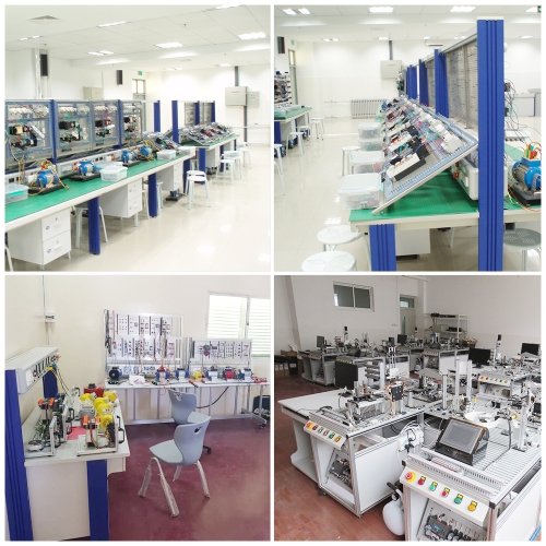
This equipment takes industrial robots and machine vision as the core, organically integrates mechanical, pneumatic, motion control, frequency conversion speed regulation, PLC control technology, modular structure, easy to combine, to achieve rapid detection and assembly of different materials. In order to facilitate practical training and teaching, the system has been specially designed to complete various types of robot individual training and comprehensive project training, and to complete various types of robot individual training and comprehensive project training. Six-axis robot teaching, positioning, grasping, assembly, storage and other training can be carried out,
It includes six-degree-of-freedom industrial robots, intelligent visual inspection systems, PLC control systems, and a set of feeding, conveying, assembling, and warehousing mechanisms, which can implement operations such as sorting, testing, handling, assembly, and storage of workpieces.
The components of the platform are all installed on the profile table. The mechanical structure, electrical control circuit and actuator are relatively independent, and are designed with industrial standard parts. Through this platform, it can be trained in various aspects such as mechanical assembly, electrical circuit design and wiring, PLC programming and debugging, intelligent visual process editing, industrial robot programming and debugging applications, and is suitable for vocational colleges and technical school automation related majors. The practical training of courses such as "Control Technology" and "Automation Technology" are suitable for automation technicians to conduct engineering training and skill competitions.

2. Equipment structure and composition
The training platform consists of a six-degree-of-freedom industrial robot system, an intelligent visual inspection system, a programmable controller (PLC) system, a feed unit, a conveyor unit, a feed waste temporary storage unit, a processing waste temporary storage unit, a workpiece assembly unit, It consists of warehouse unit, various workpieces, profile training table, profile computer desk, etc.
1. Six degrees of freedom industrial robot system
It is composed of a robot body, a robot controller, a teaching unit, an input-output signal converter, and a grasping mechanism. It is equipped with pneumatic grippers and can carry out operations such as handling, assembly, and disassembly of workpieces. 
1) The robot body is composed of six-degree-of-freedom joints and is fixed on the profile training table. It has 6 degrees of freedom. The installation methods of the series-joint-type industrial robot include ground installation, hanging installation, and inverted installation.
2) The working range of the first axis is +170°/-170°, the maximum rotation speed is 370°/s
3) The working range of the second axis is +110°/-110°, the maximum rotation speed is 370°/s
4) The working range of the third axis is +40°/-220°, the maximum rotation speed is 430°/s
5) The working range of the 4th axis is +185°/-185°, the maximum rotation speed is 300°/s
6) The working range of the 5th axis is +125°/-125°, the maximum rotation speed is 460°/s
7) The working range of the 6th axis is +360°/-360°, the maximum rotation speed is 600
8) The maximum working radius is 500mm
9) Payload 5kg
10) The robot teaching unit has an LCD screen, an enable button, an emergency stop button, and an operation keyboard, which are used for parameter setting, manual teaching, position editing, program editing and other operations.

2. Intelligent visual inspection system
Equipped with a set of intelligent vision system, which is composed of vision controller, white light source, vision camera and monitoring display. It is used to detect the characteristics of the workpiece, such as numbers, colors, shapes, etc., and can also perform real-time detection operations on the assembly effect. It is connected to PLC or robot controller through I/O cable, and also supports serial bus and Ethernet bus to connect to PLC or robot controller to transmit test results and test data.
3. Siemens programmable controller unit
Equipped with Siemens S7-1200 programmable controller, it comes with Ethernet communication module, digital expansion module to control the action of robot, motor, cylinder and other actuators, process the detection signals of each unit, manage the work flow, data transmission and other tasks.
4. Feeding unit
It is composed of hopper, rotary table, material guide mechanism, workpiece slide, switching power supply, programmable controller, button, I/O interface board, communication interface board, electrical mesh plate, and DC gear motor. Return to the feeding table and send it to the testing station in turn.
5. Conveying unit
Contains a set of AC speed control system, which is composed of frequency converter, three-phase AC motor, conveyor belt, fiber optic sensor, etc., installed on the profile training table, used to transfer workpieces.
6. Workpiece assembly unit
It is composed of workpiece optical fiber sensor, processing table, cylinder, small materials, etc. It is installed on the conveyor belt and is used to assemble the workpiece.
7. Warehouse unit
Composed of aluminum profiles and machine glass
8. Temporary storage of waste products
It is installed on the profile training table, and temporarily stores abnormal materials for feeding and abnormal materials for processing.
Fourth, the configuration list (call to obtain)

5. Practical training projects
1. Principle, use and debugging of machine vision system
2. The principle, use and debugging of the six-axis industrial robot system
3. Calibration and mutual conversion between the six-axis industrial robot coordinate system and the machine vision coordinate system
4. Installation and commissioning of integrated applications of industrial robots and machine vision systems
5. Machine vision system template setting, programming and debugging
6. Manual debugging of industrial robots through the teaching unit
7. Set and modify the coordinates of each control point through the teaching unit
8. Write and modify industrial robot programs through the teaching unit
9. Robot tracking coordinate setting
10. Software development and programming of industrial robot system

11. Intelligent visual image input editing and debugging
12. Intelligent visual results for editing and debugging
13. Intelligent visual color comparison measurement
14. Intelligent visual number comparison measurement
15. Smart visual size comparison measurement
16. Intelligent visual angle measurement
17. Integrated application of intelligent vision system and industrial robot
18. PLC program programming and debugging
19. Integrated application of intelligent vision system and industrial robot
20. Connection of inverter and main circuit of AC motor
21. Parameter setting and operation of the inverter panel
22. Frequency converter panel controls AC motor speed regulation
23. Control the motor start and stop through the external terminal of the inverter
24. Installation of pneumatic direction control loop
25. Installation of pneumatic speed control loop
26. Installation of pneumatic sequence control loop
27. Pneumatic system gas circuit connection
28. Position adjustment of auto switch
39. Pneumatic system debugging